We already had an Acton (now Princeton Instruments) FA-448 filter wheel connected to our 30Hz intensified (as in night-vision) CIDTEK camera, so my task was to modify the wheel to switch filters in sync with the camera's frame-rate. The original position controller the wheel shipped with had insufficient documentation for hacking, and the stepper motor couldn't keep the wheel going as fast as we needed, so the controller was gutted for upgrade.


The Acton FA-448 opened up, and the wheel loaded with filters which transmit only a narrow color band. The blue one is for a boron III emission, and the green ones are all for different flavors of molybdenum I.
The stepper motor was a standard NEMA-17 size, so I replaced it with a two-phase high current low inductance model (4209L-09) and a matching controller (R525) from Lin Engineering. This needed a 50VDC power supply rated at 3A so I got a 150W switching supply (PW-150-48), and used a separate 5VDC/1A supply we had lying around to power the optical isolators on the controller. To control the stepping and sync with the camera I used an Arduino Leonardo, and wired up the whole thing as shown below.


I needed to smoothly spin up the wheel to avoid the motor skipping pulses, which can happen if it doesn't have enough torque for the pulse times. This is avoided by programming a sequence of decreasing delays between pulses so that less than the available torque is used. To figure out the pulse times, I wrote a quick Matlab script to integrate the equations of motion for the wheel/gear/motor inertia using some fixed fraction of the manufacturer's torque curve, which spins up the wheel without skipping ANY steps. I confirmed this by spinning the wheel up, rotating at speed for 10 revolutions, then spinning it down, and observing that it returns to the same position as it started (see video above). To save RAM on the Arduino (only 1kB!), the ~1000 element array is stored in program memory and retrieved one element at a time.
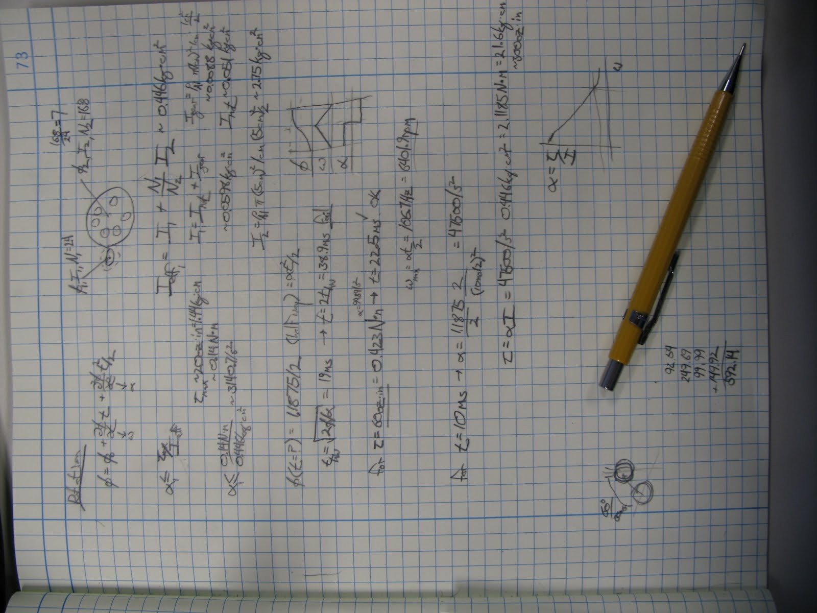

Equations of motion for the system and the motor torque curve
The biggest trouble I had was getting the timer based interrupts to work which apparently is a non-trivial application of the Arduino. Finding even the interrupt vectors took a bit of hunting through the ATmega32u4 datasheet, but they were in there. I used the hardware based timers for accurate timing of motor steps, and an interrupt service routine to change the pulse time for the next step.
After the wheel spins up, I use a second hardware interrupt triggered by incoming frame init pulses to determine if the wheel is spinning a bit too fast or too slow, and to gate the intensifier for different durations depending on the filter position. The brightness of different spectral regions and respective filter transmissions can vary by many orders of magnitude: prior knowledge we used to optimize the scene exposure. This was controlled by yet another timer. Since the interval between frame init pulses (33ms) is so much longer than the typical gate time (1ms), the timer overflows between pulses and sets the interrupt flag. This flag needs to be cleared before the interrupt is enabled, otherwise it will trigger the interrupt on the next clock cycle.


Upgraded camera system installed at the MIT Alcator C-Mod tokamak, and the author feeling serious after installation
No comments:
Post a Comment